
|
Dataforth Application Note - Basic Bridge Circuits
March 2018,
MARIETTA, GA ~
Preamble
This application note will focus primarily on some subtleties of bridge circuit excitation and associated performance. Analysis of all the many bridge topologies that compensate for small second order effects are beyond the scope of this application note. Readers interested in the in-depth details of complex bridge topologies and strain gage applications should explore the internet, which contains thousands of sites dedicated to such details. In addition, readers are encouraged to examine Dataforth’s complete line of Signal Conditioning Modules (SCMs) dedicated to strain gage bridge applications, Reference 1.
Basic Bridge Circuits
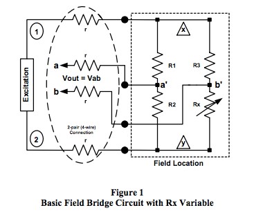
Analytical investigations throughout this document focus on the R-ohm type bridge, which means all bridge resistors are “R” ohms when not exposed to the field process variables. Figure 1 represents the R-ohm bridge type field sensor with all bridge resistors (R1, R2, R3, Rx) located at the point of field measurement; however, as resistor Rx is the bridge resistive sensor element, it varies with process parameters such as temperature, flow, pressure, level, humidity, strain, etc. In R-ohm bridge topologies, R1, R2, R3 are equal to R and Rx = (R+Ä R) where Ä R is a function of process variables.
Examples
To read Dataforth's complete application note, please
click here. |